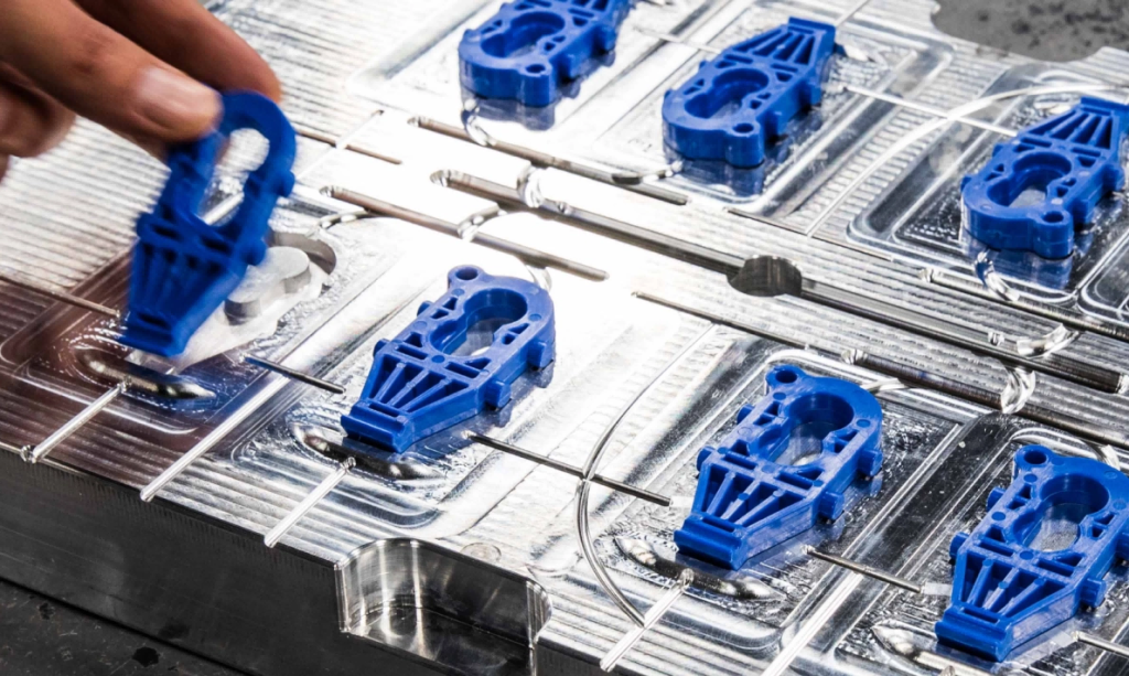


In the field of CNC machining, there is a wide range of machine configurations, innovative design solutions, cutting speed options, dimensional specifications, and types of materials that can be processed. However, not every design can seamlessly integrate with every machining process. Similarly, not all features can be precisely machined to any desired dimension, and not all material types can withstand cutting speeds of any magnitude. Inappropriate combinations of incompatible designs with cutting speeds or specific features with required dimensions can potentially lead to safety hazards or some form of machining failure.
To guide the implementation of machining processes, a series of standards have been established. Some of these standards are derived from long-term trial and error and accumulated practical experience, while others are the result of carefully planned scientific experiments. In addition, some standards have been officially recognized by the International Organization for Standardization (ISO) and enjoy international authority. Other standards, although not official, are widely known and adopted within the industry, with slight variations.

Design Standards
Design standards are non-official guidelines specifically designed to guide the computer-aided design (CAD) phase of CNC machining processes. These standards primarily focus on the geometric shape specifications of parts. It is important to note that these standards are merely recommended references, and their specific application may vary depending on the performance of CNC machines and the different practices of machining companies.
1. Wall Thickness
During the machining process, vibrations may cause components with insufficient wall thickness to fracture or deform, a phenomenon that is particularly pronounced in materials with low stiffness. Generally, the standard minimum wall thickness for metal walls is set at 0.794 millimeters, while the standard minimum wall thickness for plastic walls is 1.5 millimeters.
2.Hole/Cavity Depth
Excessively deep cavities can make milling operations difficult to perform effectively, possibly due to excessive tool overhang or tool deflection. In some cases, the tool may even fail to reach the surface that needs to be machined. To ensure machining quality, the minimum depth of a cavity should be at least four times its width. For example, if a cavity is 10 millimeters wide, its depth should not exceed 40 millimeters.
3. Holes
When designing holes, it is recommended to reference existing standard drill bit sizes for planning. Regarding hole depth, it is generally recommended to follow the standard depth of four times the diameter. However, in some cases, the maximum depth of a hole can be extended to ten times the nominal diameter.
4. Feature dimensions
For tall structures such as walls, a critical design standard is the ratio of height to thickness (H:L). Specifically, this means that if a feature has a width of 15 millimeters, its height should not exceed 60 millimeters. Conversely, for small features (such as holes), dimensions can be as small as 0.1 millimeters. However, for practical application considerations, 2.5 millimeters is recommended as the minimum design standard for these small features.
5.Part Dimensions
Currently, ordinary CNC milling machines are widely used and can typically process workpieces with dimensions of 400 millimeters x 250 millimeters x 150 millimeters. CNC lathes, on the other hand, can typically process workpieces with a diameter of Φ500 millimeters and a length of 1000 millimeters. When dealing with large parts measuring 2000 millimeters x 800 millimeters x 1000 millimeters, ultra-large CNC machine tools must be used for processing.
6.Tolerances
Tolerances are a critical consideration in the design process. However, it is important to note that tolerances should be focused on critical features, as overly generous tolerances can significantly increase processing time and costs. The tolerances specified in the design should be determined based on the tolerance capabilities of the CNC machine tool being used. Although it is technically possible to achieve precision tolerances of ±0.025 millimeters, in practice, 0.125 millimeters is typically considered the standard tolerance range.
ISO Standards
ISO standards are official specifications formally recognized by the International Organization for Standardization. In the field of CNC machining, there are hundreds of ISO standards to follow. The following are some of the most critical standards.
1. ISO 230
This is a series of 10 standards that define the geometric accuracy, numerical control axis accuracy and repeatability, thermal effects, noise emissions, and vibration levels during machining of machine tools operating under quasi-static or no-load conditions.
2. ISO 229:1973
This standard is specifically designed to specify the speed settings and feed rates for CNC machine tools.
3. ISO 369:2009
On the machine body of CNC machine tools, certain symbols and instructions are typically marked. This standard clarifies the specific meanings of these symbols and their corresponding explanations.
Debaolong Seiko memiliki kontrol manajemen yang ketat terhadap seluruh proses, mulai dari pesanan pelanggan, mulai dari produksi hingga pengujian dengan kontrol teknik standar. Kami adalah pemasok manufaktur yang dapat diandalkan.